Steel Wire Rope Explained — Construction, Types, Grades and Applications
Steel wire rope construction, strand classifications (6x19, 6x37, 7x19), core types, finishes and selection factors for industrial lifting, rigging and mechanical applications.
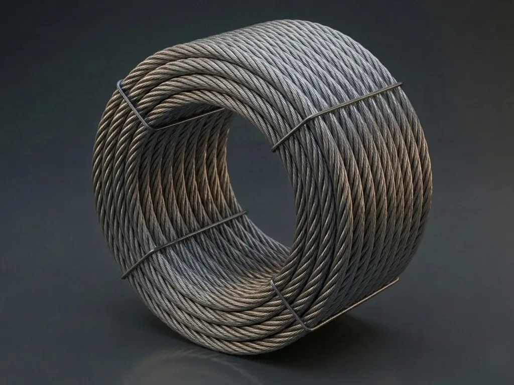
This article provides general technical reference. Wire rope construction, diameter, material and finish selection should be verified against the applicable product standard, design factor, project specification and service environment.
Steel wire rope is one of the most widely used engineered components in heavy industry. It lifts loads on cranes, hoists people in elevators, suspends platforms on offshore rigs, hauls ore in mines and transmits power between distant shafts. Its combination of high tensile strength, flexibility and predictable fatigue behaviour makes it the default choice where heavy loads must be moved, suspended or controlled.
Despite its appearance as a single twisted cable, a wire rope is a precisely engineered assembly of wires, strands and a core. The construction chosen at the specification stage determines almost every performance characteristic that follows — flexibility, abrasion resistance, fatigue life, corrosion behaviour and cost.
This article explains how steel wire rope is built, how the common construction designations (such as 6×19 and 6×37) are read, how lay pattern and core type influence behaviour, and how galvanized and stainless steel finishes compare in corrosive service.
What Is Steel Wire Rope?
A steel wire rope is a collection of steel wires arranged in a specific geometric pattern — typically helically wound into strands, which are then helically wound around a central core. The combination of high-strength steel wires and helical geometry gives the rope a useful combination of properties:
- High tensile strength at relatively low weight
- Flexibility that allows it to bend over sheaves and drums
- Predictable fatigue behaviour under repeated bending and tension
- Resistance to abrasion, crushing and lateral pressure when properly specified
Wire rope is generally distinguished from smaller-diameter wire (often called “wire” or “cable” in commerce) by being designed for structural load-bearing roles. Industrial standards such as ISO 2408, EN 12385, GB/T 8918 and JIS G3525 all define wire rope as a stranded product intended for lifting, hoisting, suspension and similar mechanical applications.
Construction and Terminology
A wire rope is built in layers, each with a defined geometric role:
- Wire — the individual steel filament. Typically cold-drawn from high-carbon or stainless steel, with diameters ranging from 0.2 mm in fine cable constructions to several millimetres in heavy ropes.
- Strand — a bundle of wires laid helically together. A rope typically contains six or eight strands arranged around the centre.
- Core — the central element around which the strands are laid. The core may be a fibre (natural or synthetic), an independent steel wire rope, or a steel strand.
- Helix angle — the angle at which the wires and strands are laid. A larger helix angle gives more flexibility but lower effective metallic cross-section; a smaller angle gives higher strength but less flexibility.
The construction is described by a notation of the form a × b, where a is the number of strands and b is the number of wires in each strand. A 6×19 rope therefore has 6 outer strands, each containing 19 wires. Some constructions also include a filler wire arrangement (e.g. Seale, Warrington, Filler) that affects how the wires pack inside the strand.
Strand Construction: 6×7, 6×19, 6×37, 7×7, 7×19 and Others
The strand construction is the most fundamental selection parameter, because it directly governs the balance between flexibility and abrasion resistance.
| Construction | Wires per strand | Typical diameter range | Flexibility | Abrasion resistance | Typical applications |
|---|---|---|---|---|---|
| 6×7 | 7 | 6 – 36 mm | Low | Very high | Mine hoists, guy lines, track cables |
| 6×19 | 19 | 6 – 46 mm | Medium | High | Cranes, slings, general rigging |
| 6×37 | 37 | 6 – 60 mm | High | Medium | Cranes with multiple sheaves, hoists |
| 7×7 | 7 | 3 – 12 mm | Very low | High | Guys, stays, antenna cables |
| 7×19 | 19 | 3 – 32 mm | High | Medium | Control cables, winch lines, aircraft cable |
| 8×19 | 19 | 6 – 32 mm | Medium | High | Crane hoist ropes, bucket elevators |
The general principle is that more, thinner wires increase flexibility and fatigue resistance but reduce abrasion resistance, because each individual wire is smaller and more easily worn by surface contact. Conversely, fewer thicker wires (6×7, 6×19) resist surface wear better but are stiffer and tolerate fewer bends before fatigue failure.
Compound constructions (Seale, Warrington, Filler) modify this trade-off. A Seale strand has outer wires of larger diameter than the inner wires, improving abrasion resistance without sacrificing all the strength. A Warrington strand alternates large and small outer wires, giving a balance between abrasion and flexibility. Compound constructions are widely used in 6×19 and 6×36-class ropes and are usually specified by name in addition to the basic construction designation.
Lay Patterns: Regular Lay, Lang Lay and Alternate Lay
The “lay” of a rope describes the direction in which the strands are wound around the core, and the relationship between the strand lay and the wire lay inside the strand.
- Regular lay — strands are laid in one direction and the wires inside each strand are laid in the opposite direction. This is the most common construction. It is less prone to rotation and unlay under load.
- Lang lay — strands and wires are laid in the same direction. Lang lay rope has higher fatigue resistance and better abrasion resistance because the wearing surface of each wire is presented to the sheave more gradually. However, it tends to rotate under load and is more sensitive to drum spooling.
- Right lay and left lay — describes the direction (clockwise or anti-clockwise) of the outer strand helix. Right regular lay is the default in most markets.
For general-purpose lifting, regular lay is preferred because of its predictable handling and lower rotation tendency. Lang lay is selected where the rope passes over many sheaves and where maximum fatigue life is required, provided that rotation is acceptable.
Core Types: Fibre Core, IWRC and WSC
The core occupies the centre of the rope and serves two functions: it supports the strands so they retain their geometry, and it may contribute to the rope’s strength and crush resistance.
- Fibre Core (FC) — natural or synthetic fibre (sisal, polypropylene, polyamide). Fibre cores hold lubricant, improve flexibility and dampen internal friction. They are standard for general-purpose rope in non-critical applications. Temperature sensitivity is the main limitation.
- Independent Wire Rope Core (IWRC) — a separate wire rope of its own construction is used as the core. IWRC ropes have higher strength, better heat resistance and higher resistance to crushing. They are the default for crane duty and for high-temperature environments.
- Wire Strand Core (WSC) — a single steel strand forms the core. WSC sits between FC and IWRC in performance and is used where a moderate strength increase over FC is needed without moving to a full IWRC design.
For hot environments (furnace charging, slag handling, certain foundry operations) IWRC is typically mandatory. For outdoor cranes and rigging, IWRC is also common because it tolerates the higher contact pressures of multi-layer drum spooling.
Materials and Finishes
The wires themselves may be supplied in several finishes, each with a different balance of strength, fatigue and corrosion resistance:
- Bright (ungalvanized) wire — drawn from carbon steel and supplied with a light oil film. Bright wire rope has the highest fatigue performance because the steel surface is unbroken by a coating. It is the lowest-cost option and is used indoors or where corrosion is controlled.
- Galvanized wire — zinc-coated by hot-dip or electrogalvanizing. The zinc coating sacrifices to protect the underlying steel, giving significantly longer service life in outdoor or damp environments. Galvanizing reduces fatigue life slightly compared with bright wire because the coating introduces micro-notches at the wire surface, but the trade-off is usually favourable in any environment where corrosion would otherwise limit service life.
- Stainless steel wire — drawn from austenitic stainless grades, typically AISI 304 (1.4301) or AISI 316 (1.4401). Stainless steel wire rope is used where corrosion resistance is the primary requirement and where the higher cost is justified — marine rigging, architectural tensioning, food processing, pharmaceutical equipment and chemical exposure.
Galvanizing classes (commonly designated Class A or Class B per ASTM A741 and EN 10264) describe the thickness of the zinc coating. Class B is the heavier coating, used in more aggressive environments.
Galvanized vs Stainless Steel Wire Rope
The two most commonly specified corrosion-resistant finishes are often confused. Their behaviour and cost are not interchangeable.
| Property | Galvanized wire rope | Stainless steel wire rope |
|---|---|---|
| Base material | Carbon steel wire, zinc-coated | Austenitic stainless (304 / 316) |
| Corrosion mechanism | Zinc sacrifices to protect steel (cathodic protection) | Passive Cr-oxide layer resists corrosion |
| Typical environments | Outdoor, marine-adjacent, industrial atmosphere | Marine immersion, chemical, food-grade, architectural |
| Strength | Comparable to bright wire | Slightly lower (stainless grades are softer) |
| Fatigue life | Slightly reduced vs bright | Comparable to bright in clean service |
| Cost | Moderate | Significantly higher |
| Lifespan in corrosive service | Multi-year, depending on coating class and exposure | Long, often 2–5× galvanized in the same exposure |
| Typical standards | ASTM A741 1, EN 10264 | EN 12385, JIS G3525 |
For most industrial lifting and rigging in outdoor service, galvanized wire rope is the standard. Stainless steel wire rope is reserved for applications where the corrosion environment is too aggressive for galvanizing, or where metallic contamination is unacceptable (food, pharmaceutical, cleanroom).
A common mistake is to use galvanized rope in submerged marine service. In long-term seawater immersion, the zinc coating is consumed relatively quickly and the underlying steel begins to corrode. For permanently submerged or splash-zone service, stainless steel 316 rope (or specialised synthetic rope) is normally specified.
Strength, Diameter and Breaking Load
The two most important mechanical parameters are rope diameter and minimum breaking load (MBL).
The MBL is the calculated force at which a new, unused rope is expected to fail under a static tensile test. It is determined by the wire tensile strength, the metallic cross-section of the rope, and the construction factor. Approximate values for common constructions:
- 6×19 class, 1960 MPa wire grade: MBL ≈ 0.33 × d² × Rr (kN, with d in mm and Rr in MPa)
- 6×37 class, 1960 MPa wire grade: MBL ≈ 0.29 × d² × Rr (kN)
These factors are rope-class averages and the exact value depends on the strand construction (Seale, Warrington, Filler). Detailed values are tabulated in ISO 2408 2 and EN 12385-4 3.
In service, a rope is never loaded to its MBL. The working load is determined by applying a design factor (sometimes called a safety factor) — the ratio of MBL to the maximum working load. Common design factors are:
- 5 : 1 for general crane duty (ISO 4309, FEM 1.001)
- 3.5 : 1 for static guy ropes
- 8 : 1 or higher for personnel-carrying applications (elevators, man-riding)
Design factor selection is governed by the applicable standard, the consequence of failure, and the dynamic nature of the loading. Personnel-rated applications almost always require the highest design factors.
Standards Systems
Four standards systems dominate the global supply of steel wire rope:
- ISO 2408 2 — the international reference for steel wire ropes for general purposes. Defines construction, tensile grades, MBL calculation and dimensional tolerances.
- EN 12385 3 — the European series, with parts covering safety requirements for different rope categories (1 for general requirements, 2 for typical applications, 4 for stranded ropes).
- GB/T 8918 4 — the Chinese national standard for steel wire ropes, widely used in Asia-Pacific supply chains and on Chinese-built equipment.
- JIS G3525 5 — the Japanese industrial standard for wire ropes.
In North America, ASTM A741 covers zinc-coated wire rope specifically for highway guardrail, while many industrial lifting applications follow ASME B30.9 (slings) or specific OEM specifications. Wire used to manufacture rope is typically supplied to ASTM A1067 or equivalent.
The standards are broadly aligned in defining construction, tensile grade and MBL, but they are not automatically interchangeable. Conversion between systems is usually done on the basis of MBL and construction rather than rope designation alone.
Common Applications
Steel wire rope is used wherever high tensile load must be carried, suspended, controlled or transmitted:
- Cranes and hoists — overhead crane hoist ropes, mobile crane boom pendants, winch lines. Typically 6×19 or 6×37 IWRC, galvanized for outdoor service.
- Mining — mine hoists (often 6×7 or specialty round-strand constructions for deep shafts), dragline and shovel hoist ropes, conveyor traction cables.
- Elevators and lifts — traction sheave ropes (specialised 8×19 or 8×25 constructions), governor cables, compensating cables. Long fatigue life and dimensional consistency are critical.
- Marine and offshore — mooring lines, crane ropes on offshore vessels, life-boat launching. Galvanized or stainless steel depending on service.
- Construction and rigging — slings, guys, mast stays, crane pendant lines. 6×19 and 7×7 are common.
- Mechanical power transmission — counterweight cables, drive cables on long-distance conveyors, ski lifts and cable cars.
- Architectural and structural — tensioned cable structures, balustrade infill, suspension bridge cables (using specialized parallel-wire or strand constructions beyond the scope of this article).
Selection Guide
Selecting the right wire rope is a matter of weighing four primary factors against each other.
1. Working Load and Design Factor
Start from the maximum working load and the required design factor. The required MBL is then calculated as MBL = working load × design factor. Rope diameter, construction and wire tensile grade are chosen to deliver at least this MBL.
2. Bending and Sheave Diameter
The smallest sheave or drum the rope will pass over determines the minimum acceptable flexibility. A general rule is the D/d ratio (sheave diameter to rope diameter) — typical minimum values are 20 for general lifting, 30–40 for high-flexibility drive applications, and 25+ for elevator duty per EN 81. Smaller D/d ratios require a more flexible construction (6×37, 7×19).
3. Environment
Indoor and dry service: bright wire is acceptable and lowest cost. Outdoor industrial atmosphere: galvanized, Class B for aggressive environments. Marine immersion, chemical exposure, food or pharmaceutical: stainless steel, typically 316 for marine and 304 for general corrosion resistance.
4. Abrasion and Fatigue
If the rope runs over sheaves or drums in continuous operation, fatigue is the dominant failure mode — choose a construction with more, thinner wires (6×37, 7×19) and an IWRC for higher contact pressures. If the rope sees external abrasion (drag, scraping, sand): choose a construction with fewer, thicker wires (6×19, 6×7) and an abrasion-resistant compound strand design (Seale).
A practical selection workflow:
- Define working load and required design factor.
- Calculate required MBL and select rope diameter and tensile grade.
- Check D/d ratio against the smallest sheave/drum in the system.
- Match environment to finish (bright / galvanized / stainless).
- Match duty cycle to construction (flexible for high cycles, rugged for abrasion).
- Specify end connections (spliced eye, swaged socket, wedge socket, mechanical clamp) consistent with the rope design and the standard in force.
Inspection, Handling and End Connections
Wire rope in service should be inspected at defined intervals. Most standards (ISO 4309 for cranes, ASME B30.9 for slings) define retirement criteria based on the number of broken wires in a given rope length, reduction in rope diameter, corrosion, deformation and heat damage. In the United States, OSHA 1926.1413 6 provides the regulatory reference for inspection and replacement criteria on construction and industrial sites.
Common end-connection methods include:
- Spliced eye — formed by unlayling and re-laying the strands back into the rope. Highest strength retention, requires skilled fabrication.
- Swaged socket — a metal socket is mechanically pressed onto the rope end. Used for permanent terminations on crane ropes.
- Wedge socket — uses a wedge to lock the rope in a socket body. Lower cost, suitable for guy ropes and static applications.
- Mechanical clamp (wire rope clip) — U-bolt or fist-grip clamps. Used for temporary terminations and guy ropes. The number and torque of clips are specified in standards such as ASME B30.9 and EN 13414-1.
Lubrication during service extends fatigue life. The core and inter-strand spaces are typically re-lubricated at scheduled intervals using a wire-rope-specific lubricant that penetrates the rope interior.
Conclusion
Steel wire rope is a deceptively simple product whose performance is governed by a small number of well-defined parameters. Construction (6×7, 6×19, 6×37, 7×19) determines the balance between flexibility and abrasion resistance. Lay pattern and core type add finer control over rotation, fatigue and crush resistance. Material and finish — bright, galvanized or stainless — determine corrosion behaviour and cost.
For a typical industrial lifting or rigging application, the selection process follows the same sequence: define the working load and design factor, calculate the required minimum breaking load, choose diameter and grade, match the construction to the sheave and duty cycle, and match the finish to the environment. The standards — ISO 2408, EN 12385, GB/T 8918, JIS G3525 — provide the engineering data to make each step quantifiable.
For a deeper look at how galvanized wire rope is specified, see Galvanized Steel — Corrosion Protection for Industrial Applications. For background on the steel wire itself, see Hot Rolled vs Cold Rolled Steel.
References
-
ASTM International, ASTM A741/A741M — Standard Specification for Metallic-Coated Steel Wire Rope and Fittings for Highway Guardrail. ASTM A741 ↩
-
International Organization for Standardization, ISO 2408:2017 — Steel wire ropes for general purposes — Requirements. ISO 2408 ↩ ↩2
-
European Committee for Standardization, EN 12385 (series) — Steel wire ropes — Safety. EN 12385 ↩ ↩2
-
Standardization Administration of China, GB/T 8918 — Steel wire ropes for important purposes. GB Standards ↩
-
Japanese Industrial Standards Committee, JIS G 3525 — Wire ropes. JSA Standards ↩
-
Occupational Safety and Health Administration, OSHA 1926.1413 — Wire Rope — Inspection and Replacement. OSHA ↩
引用形式 Wayland Steel Editorial Team (2026). Steel Wire Rope Explained — Construction, Types, Grades and Applications. Wayland Steel Insights. https://www.waylandsteel.com.cn/ja-jp/insights/steel-wire-rope-explained-construction-types-grades-applications/
工業用金属ソリューションが必要ですか?
Wayland Steel は、世界的な工業用途向けに鉄鋼製品、銅合金、アルミニウムソリューションを提供しています。